Products Category

 Solenoid Valve
 Pump
Pump
Contact Us
Name: Eva Chen
Tel: 0512-65496212
Mobile: +86-13584808209
E-mail: [email protected]
Add: No 1200 ,Xiangcheng Dadao Rd,Xiangcheng District ,Suzhou,China
Skype: Kitty080212
QQ:
2379540141


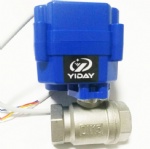
Products > Electric ball Valve > Motorized Ball Valve > Dn20 Garden Ss304 Cr201 Stainless Steel Motorized Electric Motor Ball Valve

|
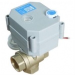
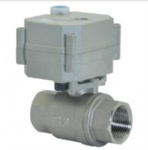
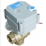
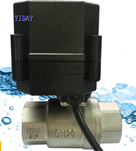
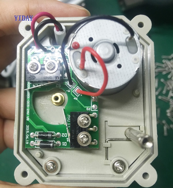
Product name : Dn20 Garden Ss304 Cr201 Stainless Steel Motorized Electric Motor Ball Valve
Product No. : 202036163221
valve size :
|
| Details: | ||||||||||||||||||||||||||||||||||||||
Technical Parameters:
YIDAY 2 way electric actuator control valve with feedback signal , DC12V/DC24V/AC100-24V , IP67,CE, NSF61, good sealing , Metal gear inside actuator . Application:Water meter , water leak detection system and water treatment etc equipment HAVC and fire works. Automatic drain system Irrigation ect small control equipment, Water drinking.Notice:1).Pls tell me the Voltage and Wires you need when you place an order.(Such You need DC12V)2).This item we need about 5~6 business day for processing! 3).If you choice using Shipping The Valve Via China Post Air Mail, We can't Promise the Delivery Time. 4).If you need NPT thread, Pls tell me in advance. Wiring diagramCR2 01 Wiring Diagram ( 2 wires control ) ·RD connect with positive, the BK connect with negative, the valve closed, the actuator automatically power off after in place , the valve remains fully closed position . ·BK connect with positive, the RD connect with negative, the valve open, the actuator automatically power off after in place, the valve remains fully open position . ﹡Suitable Working Voltage: DC5V/DC12V/DC24V ﹡Exceeding the working voltage is forbidden CR2 02 Wiring Diagram ( 2 wires control – Spring return in case of the power is failure) ·When SW is closed , the valve open. the actuator automatically power off after in place ·When SW is open, the valve closed, the actuator automatically power off after in place ﹡Suitable Working Voltage: AC/DC9-24V,AC/DC110V-230V,AC/DC9-35V(with manual override). ﹡Exceeding the working voltage is forbidden CR3 01 Wiring Diagram (3 wires control ) ·RD & GR connect with positive, BK connect with negative ·When OPEN( RD) & SW connected , the valve open, the actuator automatically power off after in place , valve remains fully open position ·When CLOSE(GR) & SW connected, the valve closed, the actuator automatically power off after in place, valve remains fully closed position. ﹡Suitable Working Voltage: DC5V/DC12V/DC24V/AC/DC9-35V ﹡Exceeding the working voltage is forbidden CR3 02 Wiring Diagram (3 wires control ) ·RD connect with positive, the BK & GR connect with negative ·SW CLOSED, the valve OPEN, the actuator automatically power off after in place. ·SW OPEN, the valve CLOSED, the actuator automatically power off after in place. ﹡Suitable Working Voltage: DC9-35V ﹡Exceeding the working voltage is forbidden CR3 03 Wiring Diagram (3 wires control) ·RD& GR connect with positive, the BK connect with negative ·SW CLOSED, the valve OPEN, the actuator automatically power off after in place ·SW OPEN, the valve CLOSED, the actuator automatically power off after in place. ﹡Suitable Working Voltage: AC/DC9-35V/AC110-230V ﹡Exceeding the working voltage is forbidden CR3 04 Wiring Diagram ( 3 wires control ) ·RD & GR connected with positive, and the BK connected with negative ·When RD & SW connected, the valve closed, the actuator automatically power off after in place , remains fully closed position ·When GR & SW connected, the valve open, the actuator automatically power off after in place , remains fully open position. ﹡Suitable Working Voltage: DC5V/DC12V/AC/DC9-35V ﹡Exceeding the working voltage is forbidden CR3 05 Wiring Diagram ( 3 wires control – Spring return in case of the power is failure) ·RD& GR connect with positive, the BK connect with negative ·SW CLOSED, the valve OPEN, the actuator automatically power off after in place ·SW OPEN, the valve CLOSED, the actuator automatically power off after in place. When external power off, the valve closed, the actuator automatically power off after in place ﹡Suitable Working Voltage: AC110-230V ﹡Exceeding the working voltage is forbidden CR4 01 Wiring Diagram (4 wires control ) 1、RD & BK are connected to the power, WT & YW are connected to the controlled wiring. 2、When the SW is closed , the valve open 3、When the SW is open , the valve closed Suitable Working Voltage::AC/DC110V-230V Exceeding the working voltage is forbidden The control wiring with power DC5V , when muitiple motorized valves are working in paralled , must put the same color control wiring together, otherwise the valve could working normally . CR5 01 Wiring diagram ( with feedback signal) 1. RD connect with positive, the BK connect with negative,the valve closed, the actuator automatically power off after in place . 2 BK connect with positive, the RD connect with negative,the valve open, the actuator automatically power off after in place . 3 GR & WT are connect when the valve open fully, YW & WT are connect when the valve closed fully Suitable Working Voltage::DC5V/DC12V/DC24V Exceeding the working voltage is forbidden CR5 02 Wiring diagram ( with feedback signal) ·When SW is closed , the valve open. the actuator automatically power off after in place ·When SW is open, the valve closed, the actuator automatically power off after in place ﹡BL & WT are connect when the valve open fully, YW & WT are connect when the valve closed fully ﹡Suitable Working Voltage: AC/DC9-24V, AC/DC9-35V, AC/DC110V-230V ﹡Exceeding the working voltage is forbidden CR7 01 Wiring Diagram ( 7 wires control with feedback signal ) ---RD connect with positive ---GR connect with SW and negative wiring --- BK connect with negative wiring ---SW open. the valve open, and keeping fully open. ---SW closed. the valve closed, and keeping fully closed. ----BL & GY connect with the valve's fully open signal wiring --- YW & WT connect with the valve's fully closed signal wiring. ﹡Suitable Working Voltage: DC5V,DC12V,DC24V,AC/DC9-35V(wide input range voltage,) ﹡Exceeding the working voltage is forbidden ※ Feedback with load ability: ① The Max. off voltage: DC36V AC220V ② The Max. off current: ≦0.4A CR7 02 Wiring Diagram ( 7 wires control with feedback signal ) 1.RD & GR connect with positive, the BK connect with negative 2. When RD & SW connected, the valve open, the actuator automatically power off after the valve fully open. 3. When GR & SW connected, the valve closed, the actuator automatically power off after the valve fully closed. 4. BL & GY connect with the valve's fully open signal wiring 5. YW & WT connect with the valve's fully closed signal wiring ﹡Suitable Working Voltage: DC5V/DC12V/DC24V ﹡Exceeding the working voltage is forbidden ※ Feedback with load ability: ① The Max. off voltage: DC36V AC220V ② The Max. off current: ≦0.4A CR7 04 Wiring Diagram ( 7 wires control with feedback signal ) ·RD & BK are connected to the power, GR & GY are connected to the controlled wiring. ·When the SW is closed , the valve open ·When the SW is open , the valve closed ·BL & GY connect with the valve's fully open signal wiring ·YW & WT connect with the valve's fully closed signal wiring. Suitable Working Voltage::AC/DC110V-230V Exceeding the working voltage is forbidden
|
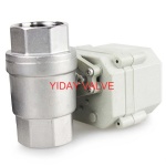
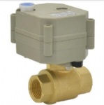
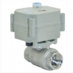
| Related Products : |