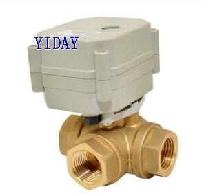
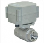
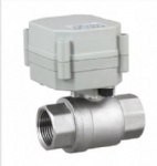
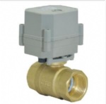
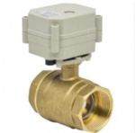
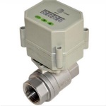
Technical Parameters:
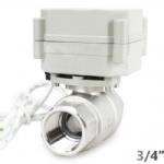
Product size NPT/BSP 1/2"
Maximum working pressure 1.3 MPa
Circulation medium Fluid, air
Rated voltageDC12V DC24V AC/DC-35V (Optional )
Wiring control methods CR2-01
Working current ≤800MA
Open/close time less than 7S
Life time 70000 times
Valve Body material: Brass
Actuator material Engineering Plastics
Sealing material EPDM & PTFE
Actuator rotation 90°
Max. torque force 2 N.m
Cable Length 0.5m,1.5m(Optional)
Environment temperature -15℃~50℃
Liquid temperature 2℃~90℃
Manual override No
Indicator Yes No
Protection class IP67
Flow direction

Wiring diagram
CR2 01 Wiring Diagram ( 2 wires control )

·RD connect with positive, the BK connect with negative, the valve closed, the actuator automatically power off after in place , the valve remains fully closed position
·BK connect with positive, the RD connect with negative, the valve open, the actuator automatically power off after in place, the valve remains fully open position .
﹡Suitable Working Voltage: DC5V/DC12V/DC24V
﹡Exceeding the working voltage is forbidden
CR2 02 Wiring Diagram ( 2 wires control – Spring return in case of the power failure)

·When SW is closed , the valve open. the actuator automatically power off after in place
·When SW is open, the valve closed, the actuator automatically power off after in place
﹡Suitable Working Voltage: AC/DC9-35V
﹡Exceeding the working voltage is forbidden
CR3 01 Wiring Diagram (3 wires control )

·RD & GR connect with positive, BK connect with negative
·When OPEN( RD) & SW connected , the valve open, the actuator automatically power off after in place , valve remains fully open position
·When CLOSE(GR) & SW connected, the valve closed, the actuator automatically power off after in place, valve remains fully closed position.
﹡Suitable Working Voltage: DC5V,DC12V,DC24V
﹡Exceeding the working voltage is forbidden
CR3 02 Wiring Diagram (3 wires control )

·RD connect with positive, the BK & GR connect with negative
·SW CLOSED, the valve OPEN, the actuator automatically power off after in place.
·SW OPEN, the valve CLOSED, the actuator automatically power off after in place.
﹡Suitable Working Voltage: DC9V-35V
﹡Exceeding the working voltage is forbidden
CR3 03 Wiring Diagram (3 wires control)

·RD& GR connect with positive, the BK connect with negative。
·SW CLOSED, the valve OPEN, the actuator automatically power off after in place
·SW OPEN, the valve CLOSED, the actuator automatically power off after in place.
﹡Suitable Working Voltage: AC/DC9-35V/AC110-230V
﹡Exceeding the working voltage is forbidden
CR3 04 Wiring Diagram (3 wires control)

·RD & GR connected with positive, and the BK connected with negative
·When RD & SW connected, the valve closed, the actuator automatically power off after in place , remains fully closed position
·When GR & SW connected, the valve open, the actuator automatically power off after in place , remains fully open position.
﹡Suitable Working Voltage: DC5V,DC12V,DC24V,AC/DC9-35V
﹡Exceeding the working voltage is forbidden
CR5 01 Wiring diagram ( with feedback signal)

1RD connect with positive, the BK connect with negative,the valve closed, the actuator automatically power off after in place .
2 BK connect with positive, the RD connect with negative,the valve open, the actuator automatically power off after in place .
3.BL & WT are connect when the valve open fully, YW & WT are connect when the valve closed fully
Suitable Working Voltage::DC12V,DC24V
Exceeding the working voltage is forbidden
CR502 Wiring Diagram ( 5 wires control – Spring return)

·When SW is closed , the valve open. the actuator automatically power off after in place
·When SW is open, the valve closed, the actuator automatically power off after in place BL & WT are connect when the valve open fully, YW & WT are connect when the valve cl osed fully
﹡Suitable Working Voltage: AC/DC9-24V,AC/DC110V-230V,
﹡Exceeding the working voltage is forbidden
CR7 01 Wiring Diagram ( 7 wires control with feedback signal )

---RD connect with positive
---GR connect with SW and negative wiring
--- BK connect with negative wiring
---SW open. the valve open, and keeping fully open.
---SW closed. the valve closed, and keeping fully closed.
----BL & GY connect with the valve’s fully open signal wiring
--- YW & WT connect with the valve’s fully closed signal wiring.
﹡Suitable Working Voltage: DC9V-35V
﹡Exceeding the working voltage is forbidden
※ Feedback with load ability:
① The Max. off voltage: DC36V AC220V
② The Max. off current: ≦0.4A
CR7 02 Wiring Diagram ( 7 wires control with feedback signal )

1.RD & GR connect with positive, the BK connect with negative
2. When RD & SW connected, the valve open, the actuator automatically power off after the valve fully open.
3. When GR & SW connected, the valve closed, the actuator automatically power off after the valve fully closed,.
4. BL & GY connect with the valve’s fully open signal wiring
5. YW & WT connect with the valve’s fully closed signal wiring
﹡Suitable Working Voltage:DC5V,DC12V,DC24V,AC/DC9-35V
﹡Exceeding the working voltage is forbidden
※ Feedback with load ability:
① The Max. off voltage: DC36V AC220V
② The Max. off current: ≦0.4A
CR7 03 Wiring Diagram ( 7 wires control with feedback signal )

·RD& GR connect with positive, the BK connect with negative。
·SW CLOSED, the valve OPEN, the actuator automatically power off after in place
·SW OPEN, the valve CLOSED, the actuator automatically power off after in place.
·BL & GY connect with the valve’s fully open signal wiring
·YW & WT connect with the valve’s fully closed signal wiring.
﹡Suitable Working Voltage: DC12V,DC24V
﹡Exceeding the working voltage is forbidden


 Solenoid Valve
 Pump
Pump