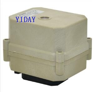
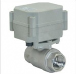
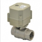
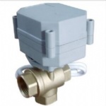
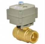
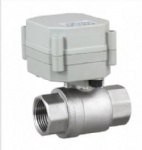
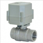
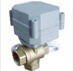
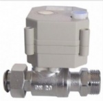
A100 Series Electric Actuator For Valve Control
Technical Parameters:
| Suitable valve size |
NPT/BSP 11/4", NPT/BSP 11/2", NPT/BSP 2" (Optional) |
| Maximum working pressure |
1.0MPa |
| Circulation medium |
Fluid, Air |
| Rated voltage |
DC12V, DC24, AC/DC9-35V, AC110-230V(Optional) |
| Wiring control methods |
CR2-01, CR2-02 , CR3-03, CR4-01, CR5-01, CR5-02,
CR7-03, CR7-04 (Optional)
|
| Working current |
≤ 800MA |
| Open/close time |
≤ 15 Sec |
| Life time |
50000 times |
| Valve Body material |
Stainless Steel 304 |
| Actuator material |
Engineering Plastics |
| Sealing material |
EPDM & PTFE |
| Actuator rotation |
90° |
| Max. torque force |
10 Nm |
| Cable Length |
0.5m,1.5m (Optional) |
| Environment temperature |
-15℃~50℃ |
| Liquid temperature |
2℃~90℃ |
| Manual override |
NO |
| Indicator |
Yes |
| Protection class |
IP67 |
Specifications:
| Model |
Wiring control |
Working voltage |
Max. torque |
| A100 |
CR2 01 |
DC12V, DC24V
|
10Nm |
| A100 |
CR2 02 |
AC/DC9-35V |
10Nm |
| A100 |
CR3 03 |
DC12V, DC24V |
10Nm |
| A100 |
CR4 01 |
AC110-230V |
10Nm |
| A100 |
CR5 01 |
DC12V, DC24V |
10Nm |
| A100 |
CR5 02 |
AC/DC12-24V |
10N.M |
| A100 |
CR7 03 |
DC12V, DC24V |
10N.M |
| A100 |
CR7 04 |
AC110-230V |
10N.M |
Wiring diagram:
CR2 01 Wiring Diagram ( 2 wires control )

·RD connect with positive, the BK connect with negative, the valve closed, the actuator automatically power off after in place , the valve remains fully closed position
·BK connect with positive, the RD connect with negative, the valve open, the actuator automatically power off after in place, the valve remains fully open position .
﹡Suitable Working Voltage: DC5V/DC12V/DC24V
﹡Exceeding the working voltage is forbidden
CR2 02 Wiring Diagram ( 2 wires control – Spring return in case of the power failure)

·When SW is closed , the valve open. the actuator automatically power off after in place
·When SW is open, the valve closed, the actuator automatically power off after in place
﹡Suitable Working Voltage: AC/DC9-35V
﹡Exceeding the working voltage is forbidden
CR3 03 Wiring Diagram (3 wires control)

·RD& GR connect with positive, the BK connect with negative。
·SW CLOSED, the valve OPEN, the actuator automatically power off after in place
·SW OPEN, the valve CLOSED, the actuator automatically power off after in place.
﹡Suitable Working Voltage: AC/DC9-35V/AC110-230V
﹡Exceeding the working voltage is forbidden
CR5 01 Wiring diagram ( with feedback signal)

1RD connect with positive, the BK connect with negative,the valve closed, the actuator automatically power off after in place .
2 BK connect with positive, the RD connect with negative,the valve open, the actuator automatically power off after in place .
3.BL & WT are connect when the valve open fully, YW & WT are connect when the valve closed fully
Suitable Working Voltage::DC12V,DC24V
Exceeding the working voltage is forbidden
CR502 Wiring Diagram ( 5 wires control – Spring return)

·When SW is closed , the valve open. the actuator automatically power off after in place
·When SW is open, the valve closed, the actuator automatically power off after in place BL & WT are connect when the valve open fully, YW & WT are connect when the valve cl osed fully
﹡Suitable Working Voltage: AC/DC9-24V,AC/DC110V-230V,
﹡Exceeding the working voltage is forbidden
CR7 03 Wiring Diagram ( 7 wires control with feedback signal )

·RD& GR connect with positive, the BK connect with negative。
·SW CLOSED, the valve OPEN, the actuator automatically power off after in place
·SW OPEN, the valve CLOSED, the actuator automatically power off after in place.
·BL & GY connect with the valve’s fully open signal wiring
·YW & WT connect with the valve’s fully closed signal wiring.
﹡Suitable Working Voltage: DC12V,DC24V
﹡Exceeding the working voltage is forbidden
CR7 04 Wiring Diagram ( 7 wires control with feedback signal )

·RD & BK are connected to the power, WT & YW are connected to the controlled wiring.
·When the SW is closed , the valve open
·When the SW is open , the valve closed
·BL & GY connect with the valve’s fully open signal wiring
·YW & WT connect with the valve’s fully closed signal wiring.
Suitable Working Voltage::AC/DC110V-230V
Exceeding the working voltage is forbidden
|


 Solenoid Valve
 Pump
Pump